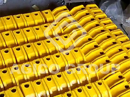
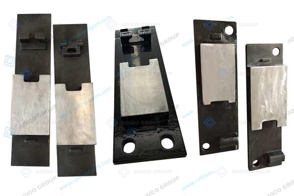
A slide baseplate supports the rails in the switch area of a railway turnout and provides a working surface for switch-rail movement. When its welds separate, its body cracks or its sliding surface deteriorates, both rail support and turnout operation can be affected. Understanding the surrounding support and fastening conditions is therefore as important as identifying the damaged plate.
Four recurring problems are weld separation, baseplate fracture, fracture of the stock-rail hold-down and corrosion or scoring of the sliding surface. These problems can have several interacting causes. Replacing a damaged component without checking rail pads, fastening interfaces, rail geometry and support levels can leave the original loading problem unresolved.
Why Metro Turnouts Can Be Demanding for Slide Baseplates
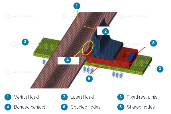
In the metro arrangements discussed here, a relatively stiff slab track transfers part of the cushioning function to the pads beneath the baseplate and stock rail. Pad condition and support contact influence how the assembly responds to repeated wheel passages. Compact turnout geometry and lateral loading during curved movements can further challenge the support arrangement.
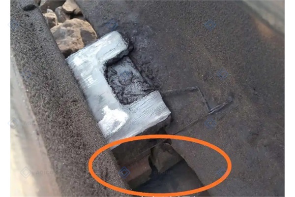
Once a crack exists, repeated loading may promote further damage. Its rate of growth depends on the component, loading, material and support conditions. A photograph alone cannot establish whether continued operation is acceptable; assessment and corrective action belong within the operator's approved maintenance procedure.
Traffic frequency also matters. As an illustrative calculation, a train with 24 wheelsets passing every three minutes over a 15-hour operating day gives 300 train passages and 7,200 wheelset passages. If the same 24-wheelset assumption is applied to 650 train passages, the total becomes 15,600 wheelset passages. These are exposure counts, not measured impact forces, stress cycles at a particular location or a prediction of fatigue life.
Slide Baseplate Weld Separation
In a conventional welded design, the sliding table is joined to the baseplate by welds. The connection has to transfer forces while the stock rail, switch rail and underlying pad interact under traffic. Repeated movement and local stress concentration can damage that joint, especially where the support arrangement or fastening condition allows excessive displacement.
How Rail Contact Can Affect the Welded Joint
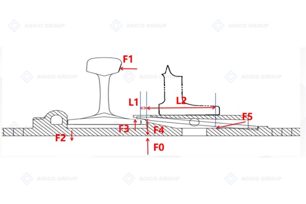
The simplified force diagram illustrates a lateral force on the stock rail, reactions at the rail seat and hold-down, vertical loading through the switch rail, a reaction through the welded connection and support from the pad below. It explains one possible load path rather than providing a complete structural calculation.
In the illustrated geometry, increasing the clearance marked L1 increases the lever arm associated with the hold-down reaction, while L2 is treated as fixed. This can increase the demand transferred through the sliding-table connection. The relationship is specific to that contact arrangement; the diagram does not establish a universal allowable gap or weld strength.
Conditions to Check Around a Separated Weld
Review loose rail fasteners, damaged sleeves, movement marks, deteriorated pads, rail-seat contact and track-gauge condition. Poor weld quality or an unsuitable weld configuration may also contribute. Several defects can coexist, so a visible weld failure should not automatically be attributed to one cause.
Record which weld has opened and whether adjacent components show similar damage. Check the fastening arrangement against the drawing and the operator's maintenance requirements. Lubrication requirements for the sliding surface should be treated separately from the requirements for fasteners and sleeves; applying oil indiscriminately is not a substitute for restoring the correct assembly condition.
Slide Baseplate Body Fracture
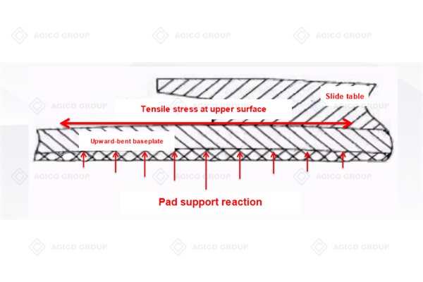
The baseplate receives downward rail loading and upward reactions from its support. If contact is uneven, the plate may bend locally rather than distribute load as intended. The resulting stress pattern depends on pad stiffness, the contact footprint, fastening restraint and plate geometry.
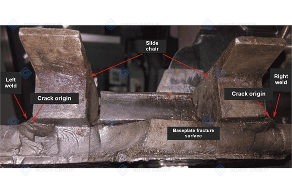
Repeated bending can initiate or extend fatigue cracks. A sudden fracture may also involve material toughness, casting defects or an existing crack, but a photograph does not establish the fracture mechanism. The simplified pad-support diagram should therefore be read as a conceptual explanation, not evidence that every plate surface undergoes the same tension-to-compression cycle.
Inspect the pad beneath the failed component and review contact marks, support levels and damage on neighbouring plates. Replacement selection should address the source of uneven loading as well as the plate itself. Keep fracture photographs and the part identification available for technical review.
Fracture of the Stock Rail Hold Down
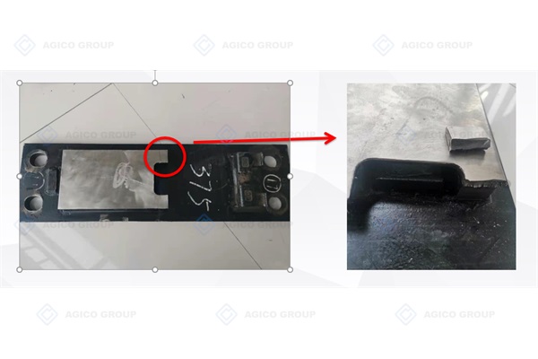
In the rigid arrangement shown, a hold-down feature overlaps the stock-rail foot and helps resist rail movement or overturning. Repeated reactions at this feature can contribute to fatigue damage. Unsuitable rail contact, abnormal lateral loading, poor geometry or inadequate material toughness may increase the risk.
The feature is called a stock-rail hold-down here to describe its function. It should not be confused with the movable switch rail. Other fastening systems use different forms of internal stock-rail restraint, so a component from one arrangement cannot be assumed to fit another.
Check the contact condition at the rail foot and the geometry of the complete restraint arrangement. Material selection and local treatment should consider toughness as well as hardness. The correct balance must be demonstrated for the offered design rather than inferred from a surface-hardness claim.
Corrosion and Scoring of Slide Baseplate Surfaces
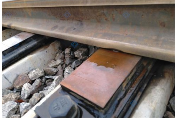
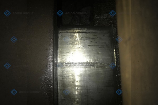
The switch rail moves across the sliding surface. Debris trapped in that interface can score the surface, while corrosion and roughness can increase resistance to movement. Differences in support level between adjacent plates may concentrate contact on individual surfaces and accelerate local deterioration.
Debris and Sliding Surface Damage
Metal fragments and other hard particles can be pressed or dragged across the working surface. Inspect scoring together with the underside of the switch rail and surrounding debris. Cleaning and lubrication must follow the applicable procedure and be accompanied by a check of the underlying support condition.
Uneven Support and Operating Resistance
Review plate levels and contact across adjacent supports. Increased switching resistance or a point-machine alarm may have several causes, including obstruction, geometry and equipment condition. Surface damage is one item to investigate, rather than a sufficient diagnosis by itself.
What an Improved Cast Slide Baseplate Can Address
A one-piece cast body removes the particular weld joining the sliding table to the baseplate. This changes that connection detail, but does not remove the need for sound material, casting integrity, dimensional control and suitable support beneath the component.
The design described uses a locally treated wear-resistant sliding area while retaining a different treatment condition at the stock-rail hold-down. The purpose is to combine resistance to surface wear with toughness in the restraint feature. Confirm the treatment process, material specification, hardness requirements and inspection method for the supplied part.
Corrosion resistance and wear resistance should be assessed against an agreed test method and the intended operating conditions. Neither a hard surface nor an integral casting alone supports an unconditional claim of rust-free, maintenance-free or unlimited-life operation. Comparative cost and performance also depend on the actual design and order scope.
What to Record Before Replacing a Slide Baseplate
Provide the approved assembly drawing, part number, plate position, rail section and left-hand or right-hand arrangement. Include dimensions, mounting-hole centres, fastening interfaces and photographs of the damaged area. Rail section alone is insufficient to establish interchangeability.
Also record the pad arrangement, measured support levels, contact condition and observed fastener or sleeve damage. State required materials, surface treatment, inspection documents, quantity and delivery destination. Any design change should be reviewed against the complete turnout assembly and accepted through the project's technical approval process.
- Approved drawing and plate position
- Rail and fastening interfaces
- Pad condition and support levels
- Damage photographs and inspection scope
For a drawing-based replacement discussion, review the cast slide baseplate product information and send the relevant drawings and site photographs to AGICO. Identifying the damage mechanism and confirming the component interfaces provides a more useful starting point than ordering by appearance alone.
Slide Baseplate Failure Questions
Does a Crack Always Mean the Same Failure Mechanism
No. Similar-looking cracks may involve different combinations of repeated bending, local contact, material condition and manufacturing quality. Inspection evidence and the surrounding assembly condition are needed before assigning a cause.
Can a Cast Plate Solve Every Turnout Support Problem
No. An integral casting removes a specific welded connection, while pads, restraint, rail geometry and installation still influence loading. The complete support arrangement needs review.
Does a Wear Resistant Surface Eliminate Lubrication
No such conclusion follows from hardness alone. Cleaning, lubrication and inspection requirements must be confirmed for the offered system and the operator's maintenance procedure.
Can a Replacement Be Selected from a Photograph
Photographs help identify the arrangement and damage, but drawings and interface dimensions are needed to establish compatibility. Include the existing pad and fastening details in the inquiry.