Railway Guard Rail for Sale
AGICO supplies railway guard rails, check rails and fabricated assemblies for switches and crossings, sharp curves, bridges, industrial sidings and renewal projects. The available program covers nominal 33 kg/m rail and the EN check-rail profiles 33C1, 36C1, 40C1, 47C1 and 48C1, plus cutting, drilling, end forming and matched accessories to approved drawings. Besides guard rails, we can also supply grooved rails for tramway and urban light rail for special uses in railway line.
- Product: railway guard rail and check rail
- Applications: bridge guard rail, switch guard rail, crossing check rail and curve restraining rail
- Profiles: nominal 33 kg/m, 33C1, 36C1, 40C1, 47C1 and 48C1
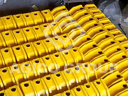
- Fabrication: cut lengths, holes, slots, chamfers, tapered or flared ends, surface protection and assembly kits
Railway Guard Rail Specifications
The following models cover common guard-rail and check-rail requirements. The C1 profiles are standardized check-rail sections under EN 13674-3. “33 kg/m guard rail” can be a commercial or legacy description and may refer to 33C1 or another project-specific section, so the cross-section and governing drawing must be confirmed before production.
| Rail model | Common designation | Nominal mass | Typical application and selection note |
|---|---|---|---|
| 33 kg/m | Confirm actual section | About 33 kg/m | Bridge guard rail, protective rail or project-specific replacement; approved drawing required. |
| 33C1 | U69 / UIC33 / RL 1-60 | 32.99 kg/m | Check rail for frogs, crossings, restraining rails and point protection. |
| 36C1 | RL 1-49 | 36.1 kg/m | Check rail for legacy and drawing-specific trackwork. |
| 40C1 | Cr 1-60U | 40 kg/m | Heavier check-rail option; verify section properties and interfaces. |
| 47C1 | Cr 4-60U | 47.1 kg/m | Robust profile for compatible switch, crossing or restraining-rail systems. |
| 48C1 | RL 1-54 | 48.3 kg/m | Heavy check-rail profile for drawing-controlled assemblies. |
Material grades, heat-treatment condition, profile tolerances, length, straightness, hole pattern and inspection requirements must follow the purchase specification. For nominal 33 kg/m guard rail, available grades may include U75V or U78CrV when confirmed by the applicable drawing and contract.
Railway Guard Rail Types and Track Functions
Switch Guard Rail for Turnouts and Crossings
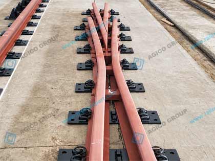
A switch guard rail or crossing check rail restrains the back of the wheel flange so the opposite wheel follows the intended path through the crossing. Consistent flangeway, correct elevation and a stable fastening arrangement are central to its function.
Railway Bridge Guard Rail
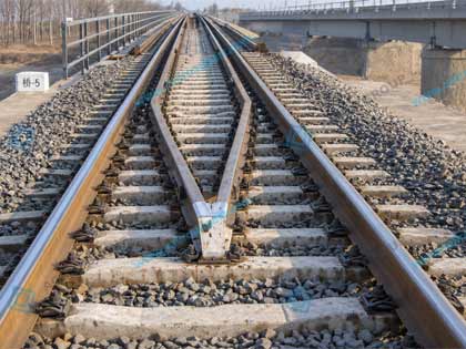
Bridge guard rails are installed inside or alongside the running rails to restrain and guide derailed wheels and help keep a vehicle within the bridge deck area. Spacing, elevation, support and end arrangement are controlled by the bridge design and railway authority requirements.
Curve Restraining Rail
On sharp curves, a check or restraining rail controls lateral wheelset movement and helps manage flange contact. The required flangeway, railhead level, entrance transition and fastening system depend on vehicle geometry, curve radius, speed, wear strategy and the approved track design.
Published installation values should not be treated as universal. The project drawing and the responsible railway authority govern the final clearances and tolerances.
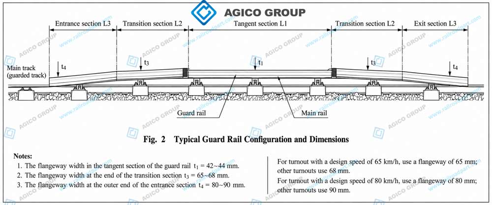
Typical Guard Rail Configuration
A guard rail commonly includes a tangent working section, transition sections and flared entrance or exit sections. The transition must guide the wheel smoothly into the working zone while maintaining the specified flangeway. Dimensions such as L1, L2, L3 and the entrance clearances must be established by the approved turnout or track drawing.
Bridge Guard Rail Nose and End Arrangement
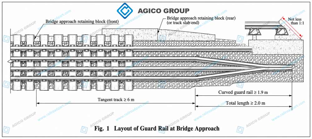
At a bridge approach, the guard rails converge through a controlled curved section and terminate in a tapered guard rail nose. This arrangement reduces the risk of a projecting rail end being struck directly and helps guide a displaced wheelset into the protected corridor.
Approach length, tangent length, taper, slope, projection and fastening details are drawing controlled. Confirm the applicable bridge standard and site arrangement before ordering replacement parts.
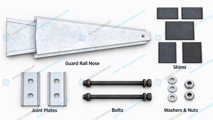
Guard Rail Accessories and Fastening Components
A complete guard-rail package may include more than the rail itself. Matching components reduce interface risk and simplify installation sequencing. Final hardware grade, torque, insulation and coating requirements must follow the approved assembly drawing and railway authority rules.
| Accessory | Purpose and quotation note |
|---|---|
| Spacers and distance blocks | Establish guard position and flangeway; confirm running-rail interface and wear allowance. |
| Brackets or support plates | Connect the guard rail to ties, bearers, baseplates or the specified structural support. |
| Bolts, nuts and washers | Supply as matched sets with confirmed diameter, grade, coating, locking method and quantity. |
| Shims | Permit controlled adjustment; quote thickness range, material and pack arrangement. |
| Insulating parts | Used where electrical separation is required; confirm signaling and environmental requirements. |
| Joint or transition plates | Connect lengths or interfaces; drill pattern and compatibility require approval. |
| End components | Tapered, machined, formed or fabricated entry and exit pieces supplied by hand and location. |
Guard Rail Installation Interface
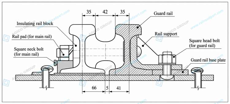
The installation interface may include a guard rail base plate, rail support, insulating block, rail pad and dedicated fasteners. Each component must match the running-rail section, guard-rail profile, sleeper or bearer arrangement and electrical requirements.
- Confirm flangeway and relative railhead elevation.
- Verify bolt-hole datums, handedness and support spacing.
- Apply the specified fastener grade, coating, locking method and torque.
- Check insulation continuity where signaling isolation is required.
Materials Fabrication and Quality Control
Material and Processing Options
- Profile and steel grade supplied to the specified standard and approved drawing.
- Cutting, straightening, drilling, slotting, chamfering and end machining.
- Tapered or flared entrance and exit ends to approved geometry.
- Brackets, spacer blocks, plates, shims and matched fastener kits.
- Surface protection, identification marking and packaging by contract.
Inspection and Documentation
Depending on the order, inspection may cover material identity, dimensions, straightness, hole position, hardness, surface condition, end geometry and assembly fit. The document package can include material certificates, traceability lists, dimensional reports, hardness reports, applicable NDT reports, packing lists and third-party inspection records.
Railway Guard Rail and Check Rail Difference
Check rail terminology: In many UK and European contexts, a check rail is installed alongside the running rail at turnouts, crossings or sharp curves to control wheelset lateral position and protect the crossing nose. In some markets, particularly in turnout terminology, the same component may be called a guard rail.
Bridge guard rail terminology: A bridge guard rail is a protective rail arrangement intended to restrain and guide derailed wheels and reduce the risk of a vehicle leaving the bridge deck. Its section, spacing and end geometry are project controlled.
Selection and Quotation Information
Provide the following information so the rail, machining and fastening interfaces can be reviewed together:
- Application: turnout, crossing, curve, bridge, depot or replacement
- Guard/check-rail profile and running-rail section
- Applicable standard, material grade and drawing revision
- Overall lengths, quantities, handedness and end orientation
- Flangeway or structural spacing and relative railhead height
- Hole centers, slots, end geometry and accessory list
- Inspection documents, surface protection and marking
- Destination, unloading limits and required delivery date
Packaging and Delivery
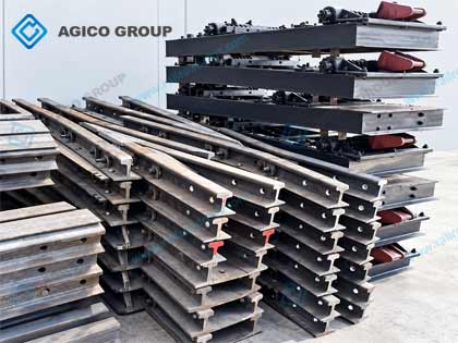
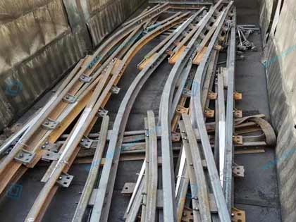
Long guard rails and fabricated assemblies are bundled and supported to limit handling damage, corrosion and distortion. End pieces, plates and fasteners can be packed and identified by assembly position. The final packing plan depends on rail length, end geometry, destination, container or breakbulk limits and site unloading equipment.
Railway Guard Rail FAQ
Is 33 kg/m the same as 33C1?
Not always. 33C1 has a published nominal mass of 32.99 kg/m and is commonly described as a 33 kg/m section, but “33 kg/m guard rail” can also be a generic or legacy description. Confirm the cross-section and designation before ordering.
Which profiles are covered by EN 13674-3?
The standard lists the check-rail profiles 33C1, 36C1, 40C1, 47C1 and 48C1. It does not automatically govern every bridge guard rail application.
Can guard rail ends be supplied tapered or flared?
Yes, subject to an approved drawing and a fabrication route compatible with the material. Provide taper length, flare geometry, orientation, hole datums and acceptance tolerances.
Can you drill holes and supply installation hardware?
Yes. Hole patterns, slots, brackets, spacers, shims and fastener kits can be supplied to approved drawings. Specify hardware grades, coatings, locking method and insulation requirements.
What inspection documents are available?
Depending on the order, the package can include material certificates, traceability lists, dimensional and hardness reports, applicable NDT reports, packing lists and third-party inspection records.
What information is needed for a replacement guard rail?
Provide the existing profile, overall length, running-rail interface, handedness, hole centers, flangeway, end geometry, photographs and the governing drawing or a measured sketch.
Request a Railway Guard Rail Quotation
Need 33 kg/m, 33C1, 36C1, 40C1, 47C1 or 48C1 railway guard rails? Send the application drawing, rail profile, quantity and delivery destination for a project-specific profile, processing, inspection and packing proposal.